
Note by author
The following is a complete chapter (11) from my book Lost Technologies of Ancient Egypt. It has been enhanced with larger color photographs and there are minor edits that do not affect the focus or tenor of the work. I decided to post it online, in order for it to be more accessible, because most of the discussion about Core 7 occurred online starting in 1995 and was prompted by my article Advanced Machining in Ancient Egypt? which was published in Analog Magazine in August of 1984 and these discussions led to further research.
At the end of this article a link is provided to the study of Core 7, and other cores at the Petrie Museum, performed by Eric Wilson and Joshua Gear, both engineers with Rolls Royce Aerospace in Indianapolis. Their study is important in that they add to the number of qualified specialists who have studied this core and determined that the grooves left by the core drill are actually spiral.
The endnotes are linked to the relevant source material and the back button can be used to return to the place they appear in the text.
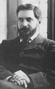
Sir. William F. Petrie in 1886
Walking in the Shadow of William F. Petrie
By
Christopher Dunn
"Where is the other evidence of this culture? Show me a potsherd. Show me a tomb. Show me an inscription. Show me any other piece of sculpture that dates from this period." ~ Mark Lehner [1]
Sir William Flinders Matthew Petrie was born in 1853 and died in 1942. In the course of his career, he wrote 102 books and he authored articles which appeared in 48 journals and 6 magazines resulting in 1024 numbered items. His shadow was cast over all who came before him and has influenced those who came later. He is considered to be the father of British Egyptology.
In 1972, Eric P. Uphill assembled materials in order to create a comprehensive bibliography of Petrie’s work. He thanks Ms. Ann Petrie, Sir William’s daughter, for allowing him to search her home for rarer articles in order to make his bibliography more complete. His introduction to the bibliography provides insight into how Petrie was viewed by his peers of that time:
Petrie died during the Second World War so that although his passing was recorded by both learned journals and the press, it did not receive the attention that would undoubtedly have been accorded it in peaceful and less difficult times. Much has been written about Petrie, perhaps the most controversial figure in the whole annals of archaeology, both during his lifetime and afterwards, and probably more eulogies both critical and uncritical have been accorded him than to any other Egyptologist since Champollion. Some have written serious analytical discussions of his work and achievements, or allegedly frank assessments of his faults, yet no one has produced a list of his publications. [2]
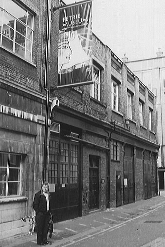
Christopher Dunn at the Petrie Museum
Professional disagreement can sometimes turn into heated debate, though such debates may not have been as public in Petrie’s day as they are now considering the development of communication technology and how it is used to promote ideas. One of the more widely known debates of the modern era was a contentious disagreement at the American Association for the Advancement of Science Convention in Chicago in 1992 between Egyptologist, Dr. Mark Lehner of the Oriental Institute, and geologist Dr. Robert Schoch of Boston University. Schoch became involved with ancient Egyptian studies when he was persuaded by John Anthony West to write an opinion on West’s claim, after Schwaller de Lubicz, that water weathering on the Great Sphinx, and especially on the Sphinx enclosure wall, was indicative of a much earlier-than-accepted date for its carving. After performing an on-site analysis, Schoch reported that the Great Sphinx is thousands of years older than scholars generally believe. Lehner called these findings “pseudoscience,” and the normal cool politeness of academic debate was thrown on the sacrificial fire as heated voices continued past the time allotted and on into the hallway after the presentation.
Lehner argued that you don't overthrow Egyptian history based on one phenomenon like a weathering profile:
"That is how pseudoscience is done, not real science." [3]
Schoch, however, held to his evaluation, which was based on the science in which he has been trained—geology—and he reiterated his studies of the Sphinx’s erosion. He used sound waves, which suggested that the monuments crevices were carved sometime between 7000 and 5000 BCE.
Scholars of Egyptian history have been scornful of Schoch’s science because it is contrary to the research that generations of Egyptologists and archaeologists have developed. Because of his understanding that people from that period were believed to be hunter-gatherers who had not advanced sufficiently to build cities like those of the ancient Egyptians, Lehner asked for evidence of a culture living at that time that was advanced enough to carve the Sphinx. Lehner added, however, that he was willing to consider evidence, such as a potsherd, that would provide a cultural context for this lost civilization.
Dr. Schoch responded that perhaps later civilizations came on to the scene and cleaned up the area.[4] To a layperson and a scientist, this idea does not seem outlandish, considering what we know about how later cultures can absorb and mask previous cultures by destroying or corrupting evidence, as Dr. Andrews pointed out in the Foreword to Lost Technologies of Ancient Egypt. Modern societies, while living and working in the shadow of the constructions of previous generations, create artifacts that are entirely different and may give future archaeologists the wrong idea of what existed here previously should there be a break in the generational transition of knowledge. Also, when we look at the evidence highlighted in the previous chapters of this text, this idea does not sound so foreign, and it becomes obvious that more has been lost than we previously believed.
Schoch is also not the first to propose that the ancient Egyptian civilization was older than scholars believe it to be. Lehner himself benefited from followers of the sleeping prophet, Edgar Cayce, whose organization, the Association of Research and Enlightenment, funded his research in Egypt in search of the fabled lost continent of Atlantis—evidence of which was supposed to come to light in 1998. Ultimately, Lehner rejected this outside-the-box view after he failed to find evidence that Atlantis existed, and has worked diligently since to reject the ideas of those who might think that they have succeeded.
Schoch has always been careful to avoid the subject of Atlantis, and he based his evaluations strictly upon geological principles, though Lehner is known to have switched affiliations and become fully immersed in the orthodox view of history that had pulled him away from the Cayce system of belief.
The final chapter on this debate is yet to be written, but will not affect the evidence brought forward in this book. The relevance of ancient megalithic construction and precision cutting of igneous rock relies on engineering principles, not on geology or Egyptology, of which I am not an expert witness. Notwithstanding that Egyptologists are not a part of the fabric of construction and manufacturing technology today, and their counterparts in ancient times were most likely not consulted on the design and building of the Great Pyramid, if they cannot supply a credible explanation for this evidence and have it fit within the dynasties of the ancient Egyptians, then considering a non-linear view of history and a recognition that civilizations can develop and develop technologies over millennia and suffer extinction events, such as the eruption of the super volcano, Koba 70,000 - 75,000 years ago, while disturbing to consider, is a possible answer.
The potsherds Lehner asked to see that would change his mind about ancient Egyptian history are found in Egypt and in museums all over the world. The ones I have studied reside not in Egypt, but are situated in a glass display case in the Petrie Museum in London. The recent documentaries that have been broadcast by Egyptologists have been a distraction from what was really going on in ancient Egypt. They mislead by not addressing the incredible precision of the available artifacts. They do not address the remarkable geometry and exactness of the ancient Egyptians’ statues, and they have ignored evidence presented by Flinders Petrie in 1883 that proves that the ancient Egyptians used highly sophisticated methods for cutting stone—including efficient and versatile lathes.
The lathe is a natural development from the potter’s wheel depicted in ancient artwork and presumed to have existed in ancient Egypt. The type of potter’s wheel in ancient Egypt is taken from an Egyptian relief showing the god Khum seated at what is theorized to be a kick wheel.
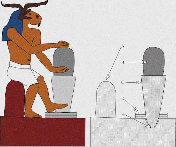
Figure 2. Egyptian relief showing the god Khum and a cross section of a potter’s wheel assembly: A. Bench B. Work C. Rotating table D. Kick wheel E. Bearing. Drawing by C. Dunn after Hodges. [5]
From the early origins of potter’s wheels, improvements evolved the technology to what we see today, and the spin-off of the potter’s wheels that are still in use are found in every manufacturing plant in the world. They have progressed from manually driven machines to water-driven and steam engine–driven line shaft pulleys and belts to the electric motor. In 1968, I was employed as a journeyman lathe turner in the tool room at the venerable J and S Eyres Ltd., engineering company in Manchester, England. This was the only company where I worked that had an old-fashioned line shaft driving several machines. Manufacturing and repairing the leather belts for the line was considered a craft in and of itself with specialists employed to perform such work.
The potsherds in the Petrie Museum, however, are of a different quality than what can be produced on a potter’s wheel or even a woodworking lathe of the kind used by undeveloped cultures. What is depicted in Figure 2 does not explain two potsherds that Petrie describes in The Pyramids and Temples of Gizeh and which are called out there as 14 D and 15 D in (Pl. xiv)
"The principle of rotating the tool was, for smaller objects, abandoned in favour of rotating the work; and the lathe appears to have been as familiar an instrument in the fourth dynasty, as it is in modern workshops. The diorite bowls and vases of the Old Kingdom are frequently met with, and show great technical skill. One piece found at Gizeh, No. 14, shows that the method employed was true turning, and not any process of grinding, since the bowl has been knocked off its centring, recentred imperfectly, and the old turning not quite turned out; thus there are two surfaces belonging to different centrings, and meeting in a cusp. Such an appearance could not be produced by any grinding or rubbing process which pressed on the surface. Another detail is shown by fragment No. 15; here the curves of the bowl are spherical, and must have therefore been cut by a tool sweeping an arc from a fixed centre while the bowl rotated. This centre or hinging of the tool was in the apex of the lathe for the general surface of the bowl, right up to the edge of it; but as a lip was wanted, the centring of the tool was shifted, but with exactly the same radius of its arc, and a fresh cut made to leave a lip to the bowl. That this was certainly not a chance result of hand-work is shown, not only by the exact circularity of the curves, and their equality, but also by the cusp left where they meet. This has not been at all rounded off, as would certainly be the case in hand-work, and it is clear proof of the rigid mechanical method of striking curves." [6]
As seen in the photographs of the bowl shard housed in the Petrie Museum, illustrated in Petrie’s drawing is the backside, convex part of a bowl shard (Figure 3 A). In my article “Advanced Machining in Ancient Egypt?” and in my book, The Giza Power Plant: Technologies of Ancient Egypt, with a chapter of the same name, I incorrectly illustrated it as a concave, dish-shaped feature. After visiting the museum and examining the artifact in question, University College London (UCL) ref. UC41398, I am now able to correct this error.
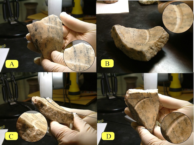
Figure 3. Petrie’s bowl shard (his 15 D) housed in the Petrie Museum, UC41398, diorite, width 2.7 inches (6.8 centimeters), length 3.8 inches (9.6 centimeters)
Petrie, however, did not discuss a more important feature of this shard: the concave surface on the opposite side of the surface he had illustrated. This is surprising, because the radial gouge on the dished side of the shard (see Figure 3 - B, C , and D) can provide a clue as to what may have caused the bowl to be knocked off axis in the lathe—or at least another result of the bowl’s displacement in the lathe. The questions it raises, however, cannot be answered by conceptualizing the lathes used in ancient time that are depicted in history books. The groove on the “dish” may have been the result of the material shifting on its axis causing the tool to plunge into the material, knocking it off-axis and causing the biaxial, convex radius on the outside of the bowl.
Because it has the impression of the geometry of the tool bit being applied to the surface, the existence of the gouge also proves Petrie’s contention that the surfaces noted on his 15 D were created with a single-point tool and were not the result of rubbing with abrasive. This is an important point when we consider the ancient Egyptians’ level of technology.
Regarding the use of a single-point tool, Petrie writes:
"That the Egyptians were acquainted with a cutting jewel far harder than quartz, and that they used this jewel as a sharp pointed graver, is put beyond doubt by the diorite bowls with inscriptions of the fourth dynasty, of which I found fragments at Gizeh; as well as the scratches on polished granite of Ptolemaic age at San. The hieroglyphs are incised, with a very free-cutting point; they are not scraped nor ground out, but are ploughed through the diorite, with rough edges to the line. As the lines are only 1/150 inch wide (the figures being about .2 [inch]), it is evident that the cutting point must have been harder than quartz; and tough enough not to splinter when so fine an edge was being employed, probably only 1/200 inch wide. Parallel lines are graved only 1/30 inch apart from centre to centre.
"We therefore need have no hesitation in allowing that the graving out of lines in hard stones by jewel points, was a well known art. And when we find on the surfaces of the saw-cuts in diorite, grooves as deep as 1/100 inch, it appears far more likely that such were produced by the jewel points in the saw than by any fortuitous rubbing about of a loose powder. And when, further, it is seen that these deep grooves are almost always regular and uniform in depth, and equidistant, their production by the successive cuts of the jewel teeth of a saw appears to be beyond question. The best examples of equidistance are the specimens of basalt No. 4, (Pl. xiv), and of diorite No. 12; in these the fluctuations are no more than such as always occur in the use of a saw by hand-power, whether worked in wood or in soft stone." [7]
Implied in the manufacturing errors in UC41398 (Figure 3) may be the action of two tools at the same time, one on the outside and one on the inside, which indicate that as the tool created the gouge on the inside of the bowl, it pushed the bowl into a component of the chuck that was holding the bowl until the stone broke under the pressure. I make this observation based on the corresponding start points of the inside gouge and the outside undercut. It is difficult to imagine, however, the multiple grooves on the outside of the dish in the sunken area all being created at the same time it took for the inside groove to travel from start depth to finish depth—but then, there are still many mysteries about ancient Egyptian technology that are not completely understood, and, in this case, without the machines to explain them, we can only speculate.
As we can see on the dished surface, the groove increases in depth until it meets the broken edge. Reference lines have been drawn on the bowl shard indicating the trueness of the radial groove. The arc describing the spherical dish radius that travels from the outside of the bowl to the center was created from three points, as noted in Figure 3 - C and D. This is drawn not to provide dimension to the piece or assert a degree of precision, but as a visual reference and evidence of the curvature.
Perhaps the most important question to ask when we try to determine how these errors were created is: What kind of power was behind the lathe to allow a single-point tool to cut a gouge so deep into the material that the stone would ultimately fail and break? The forces implied with this simple potsherd are not the forces associated with a potter’s wheel or a spindle lathe that is spun via the manual push and pull of a strung bow. If a manually operated lathe met such resistance, it would come to a stop. To argue that only manpower was used in the process of creating this error would be to argue that the operator acquired some sort of lever to rotate the chuck that held the stone and made a conscious decision to drive the tool deeper into the diorite and ruin his or her work.
Petrie’s 15 D shows the versatility of the lathe employed to create it. As seen in Figure 4, the surface is double dish shaped with tantalizing telltale shallow striations on the surface. These striations would not be out of place on a modern artifact created on a lathe when a tool, which had made a cut across the surface, was reversed across the same path it took when it made the cut. The grooves shown just below the cusp indicate that as the bowl turned in the lathe, the tool moved rapidly across the surface. Witnesses to this event are the arcs of the grooves not being concentric with the arc of the cusp and the distance between the grooves. In other words, we can clearly see that the shallow grooves do not follow the same arc as the cusp where the radius changes (see Figure 5) and are somewhat irregular. If the grooves did have the same arc as the cusp, it would mean that the tool was stationary while the bowl rotated. These grooves are also evidence of the use of a single-point tool to machine the bowl.
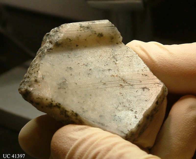
Figure 4. Petrie’s bowl shard (his 15 D), housed in the Petrie Museum, University College London, UC43197, diorite, width 2.5 inches (6.3 centimeters), height 2.3 inches (5.9 centimeters). Note the difference between this piece and figure 11.3. Figure 4 has a cusp within the dish where two radii intersect and a raised lip around the outside.
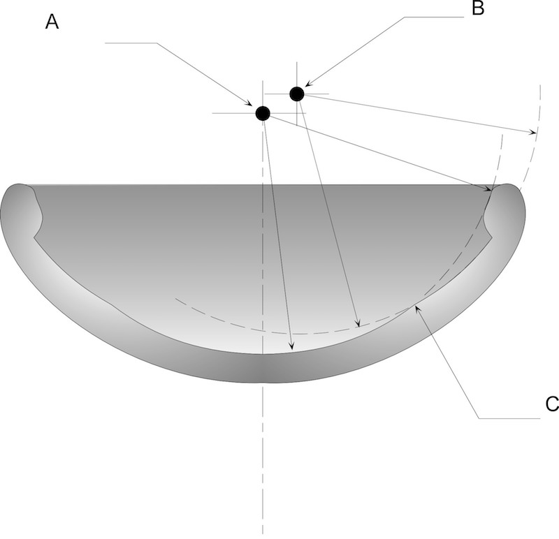
Figure 5. Petrie’s 15 D with axes of rotation for the sweep of the tool. Point A is the original pivot point of the tool. Point B is the secondary pivot point of the tool and creates the bowl's lip and the cusp (C), where the radii intersect.
When I examined these pieces physically by running a finger across the surface of the dished-out stone, they were smooth, machined surfaces with no dips or high spots. When we take these into consideration along with the sharp cusp and the scratches in the surface in Petrie’s 15 D and the deep groove in his 14 D, the implication is the use of a lathe that was under significant power and that the rotary axis of the bowl and rotation of the tool that cut Petrie’s 14 D (see Figure 11.3) and the rotary axis of the bowl in Petrie’s 15 D (see Figures 11.4 and 11.5) were dependent upon precise bearings. This technology pushes the envelope further, it is definitely not discussed in Egyptology books and moves the state of the art of ancient Egypt much higher than where Robert Moores moved it with his drag saw. The use of precise bearings would also be necessary for the proper functioning of megasaws at Abu Rawash and at Giza.
Figure 6 shows a horizontal lathe that was commonly in use the 1950s through the 1970s. Egyptologists would consider such a lathe beyond the ancient Egyptians’ capabilities. Some shops may still have such a lathe on their floor. Progress and inventiveness have seen the lathe evolve tremendously over the last fifty years. Figure 7 shows a modern Computer Numerical Control (CNC) horizontal lathe. In the span of fifty years, vast improvements have been made to our machines, though we are expected to believe that in ancient Egypt in a span of three-thousand years, they were still using sticks and stones and copper saws and drills. It seems that the evidence, not to mention human nature, proves otherwise.
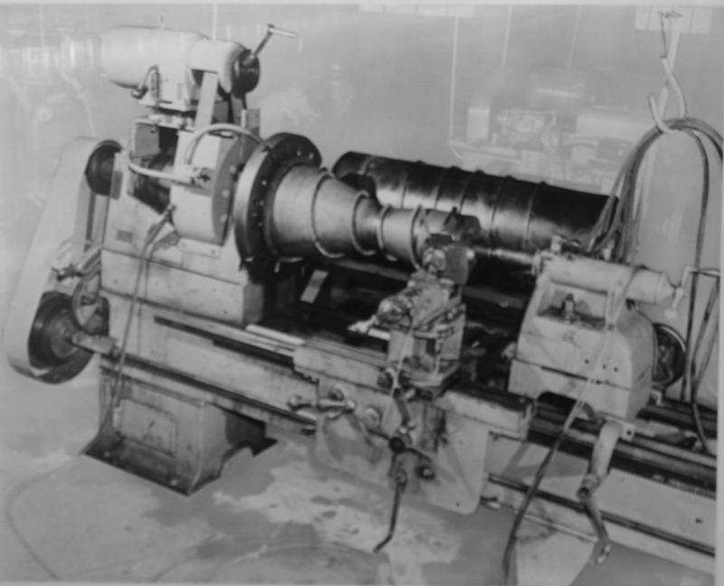
Figure 6. Horizontal engine lathe. (Courtesy, Danville Metal Stamping)
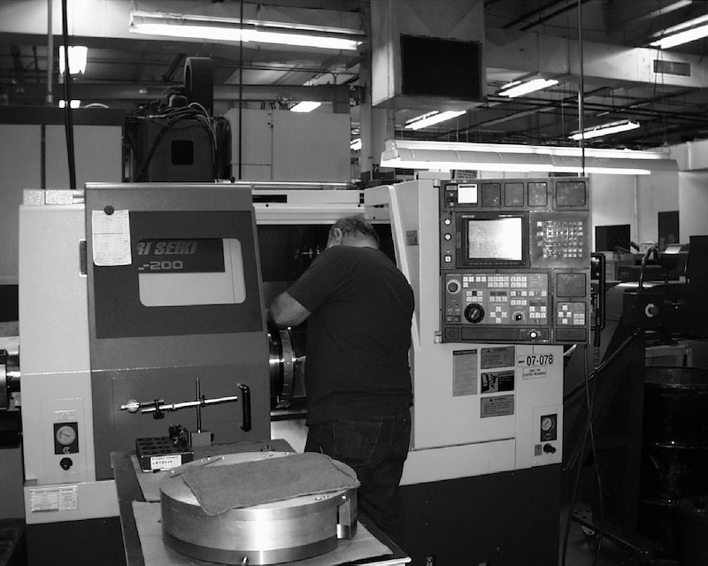
Figure 7. Horizontal CNC lathe. (Courtesy Danville Metal Stamping)
Considering that the pyramids were crafted with such precision, is it surprising to find circumstantial evidence that proves that exact and robust machine-tools existed in prehistory? Such machines did not just saw blocks for the pyramids and temples, but they also crafted delicate and precise stonework, such as the Ramses statues and the stone bowl fragments discovered by Petrie. Could we re-create the granite and basalt boxes in the Serapeum without employing some fairly sophisticated machinery? If we did not have the materials to devise such machinery, had not developed an understanding of metrology, and were without an inventory of instruments to measure precisely, how would we achieve these miracles in stone? Is anyone today willing to take on the fabrication of an Apis Bull box?
Petrie not only provides us with a cogent description of the use of lathes in ancient Egypt, a talent that most likely made his ideas controversial, he also describes an artifact that has been the topic of much discussion over the years. I became aware of the discussion after obtaining internet access in 1995 when I received an email from a man who had read my 1984 Analog Magazine article and started the discussion on dejanews.com. The original article was subsequently published in other magazines articles, the editors of which were attracted to the controversial content and that perhaps it provided answers to how the ancient Egyptians performed inexplicable feats of stone cutting. The method I had postulated is that ultrasonic machining may explain the characteristics found in a very unique artifact in Petrie’s collection.[8] This artifact is described by Petrie as 7 G (Pl. xiv); more popularly known as Core 7) and is housed in the Petrie Museum (see Figure 8). The hypothesis of ultrasonic machining stimulated both positive and negative reactions, with those that opposed the idea offering helpful suggestions on how my mind may be turned in the wrong direction.
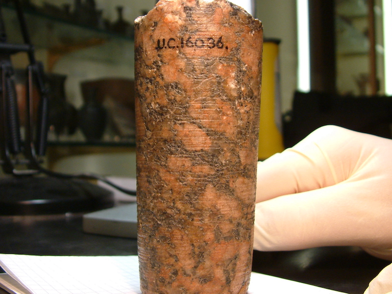
Figure 8. Petrie’s Core 7 G, housed in the Petrie Museum, University College London, UC16036, granite, height 4.33 inches (11 centimeters).
Petrie’s drawing of Core 7 and his thorough description formed the basis of my analysis. Petrie describes it:
"On the granite core, broken from a drill hole (No. 7), other features appear, which can only be explained by the use of fixed jewel points. Firstly, the grooves which run around it form a regular spiral, with no more interruption or waviness than is necessarily produced by the variations in the component crystals; this spiral is truly symmetrical with the axis of the core. In one part a groove can be traced, with scarcely an interruption, for a length of four turns. Secondly, the grooves are as deep in the quartz as in the adjacent feldspar, and even rather deeper. If these were in any way produced by loose powder, they would be shallower in the harder substance—quartz; whereas a fixed jewel point would be compelled to plough to the same depth in all the components; and further, inasmuch as the quartz stands out slightly beyond the feldspar (owing to the latter being worn by general rubbing), the groove was left even less in depth on the feldspar than on the quartz. Thus, even if specimens with similarly deep grooves would be produced by a loose powder, the special features of this core would still show that fixed cutting points were the means here employed.
"Next the Egyptians adapted their sawing principle into a circular, instead of a rectilinear form, curving the blade round into a tube, which drilled out a circular groove by its rotation; thus, by breaking away the cores left in the middle of such grooves, they were able to hollow out large holes with minimum of labour. These tubular drills vary from 1/4 inch to 5 inches in diameter, and from 1/30 to 1/5 thick. The smallest hole yet found in granite is 2 inches diameter, all the lesser holes being in limestone or alabaster, which was probably worked merely with tube and sand. A peculiar feature of these cores is that they are always tapered, and the holes are always enlarged towards the top. In the soft stones cut merely with loose powder, such a result would naturally be produced simply by the dead weight on the drill head, which forced it into the stone, not being truly balanced, and so always pulling the drill over to one side; as it rotates, this would grind off material from the core and the hole. But in the granite core, No. 7, such an explanation is insufficient, since the deep cutting grooves are scored out quite as strongly in the tapered end as elsewhere; and if the taper was merely produced by rubbing of powder, they would have been polished away, and certainly could not be equally deep in quartz as in feldspar. Hence we are driven to the conclusion that auxiliary cutting points were inserted along the side, as well as around the edges of the tube drill; as no granite or diorite cores are known under two inches diameter, there would be no impossibility in setting such stones, working either through a hole in the opposite side of the drill, or by setting a stone in a hole cut through the drill, and leaving it to project both inside and outside the tube. Then a preponderance of the top weight to any side would tilt the drill so as to wear down the groove wider and wider, and thus enable the drill and the dust to be the more easily withdrawn from the groove. The examples of tube drilling on Pl, viii. are as follow: —No. 7, core in granite, found at Gizeh. No. 8, section of cast of a pivot hole in a lintel of the granite temple at Gizeh; here the core being of tough hornblende, could not be entirely broken out, and remains to a length of .8 inch. No. 9, alabaster mortar, broken in course of manufacture, showing the core in place; found at Kom Ahmar (lat. 28° 5´), by Prof. Sayce, who kindly gave it to me to illustrate this subject. No. 10, the smallest core yet known, in alabaster; this I owe to Dr. Grant Bey, who found it with others at Memphis. No. 11, marble eye for inlaying, with two tube-drill holes, one within the other; showing the thickness of the small drills. No. 12, part of the side of a drill-hole in diorite, from Gizeh, remarkable for the depth and regularity of the grooves in it. No. 13, piece of limestone from Gizeh, showing how closely the holes were placed together in removing material by drilling; the angle of junction shows that the groove of one hole just overlapped the groove of another, probably without touching the core of the adjacent hole; thus the minimum of labour was required. The examples of tube drilling on a large scale are the great granite coffers, which were hollowed out by cutting rows of tube drill-holes just meeting, and then breaking out the cores and intermediate pieces; the traces of this work may be seen in the inside of the Great Pyramid coffer, where two drill-holes have been run too deeply into the sides; and on a fragment of a granite coffer with a similar error of work on it, which I picked up at Gizeh. At El Bersheh (lat. 27° 42´) there is still a larger example, where a platform of limestone rock has been dressed down, by cutting it away with tube drills about 18 inches diameter; the circular grooves occasionally intersecting, prove that it was done merely to remove the rock." [9]
The most startling feature of the granite core Petrie describes is the spiral groove around the core indicating a feed rate of 0.100 inch per revolution of the drill. In my article, I stated that this feed rate was five hundred times faster than modern diamond drills, which penetrate at only 0.0002 inch per revolution. This has been incorrectly interpreted by some, who have concluded that a hole of the same dimension could be drilled five hundred times faster by the ancient Egyptians than by modern drills. The correct way to describe the feed rate would be to say it was five hundred times greater than modern diamond drills, but the rotation of the drill would not have been as fast as the modern drill’s nine hundred revolutions per minute.
When I read Petrie’s description of this drill core, I tried to imagine what kind of process could replicate it. It seemed very clear that the spiral groove that wound down the core like a drunken screw (Petrie’s description) could not have been made by any loose grains rubbing on the granite. Petrie notes that the groove cut deeper through the quartz than the feldspar, which in conventional drilling would actually be the reverse, because quartz is the harder material. The taper on the core and the hole were also quite puzzling, because they did not lend to the idea that the groove was cut while a rotating tool was withdrawn from the hole. Yet the action of a tool that reflected a feed rate of .100 inch per revolution of the drill was not the work of conventional drilling as we know it and demanded consideration of other processes in its creation. All of these features were considered without the physical examination of the artifact in question and were considered phenomenal not just by me alone, but also by colleagues with whom I discussed their relevance.
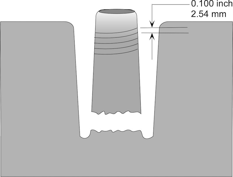
Figure 9. Egyptian core drilling hole and Core 7.
It seemed from the evidence described by Petrie that a sure way to create the spiral groove was to use a process whereby the tool oscillated, like a jack hammer or hammer drill, while it turned. I selected the method to be ultrasonic (see Figure 10), because with quartz having resonant properties, it would respond to the vibration and this might explain the deeper cut through the quartz than the feldspar.
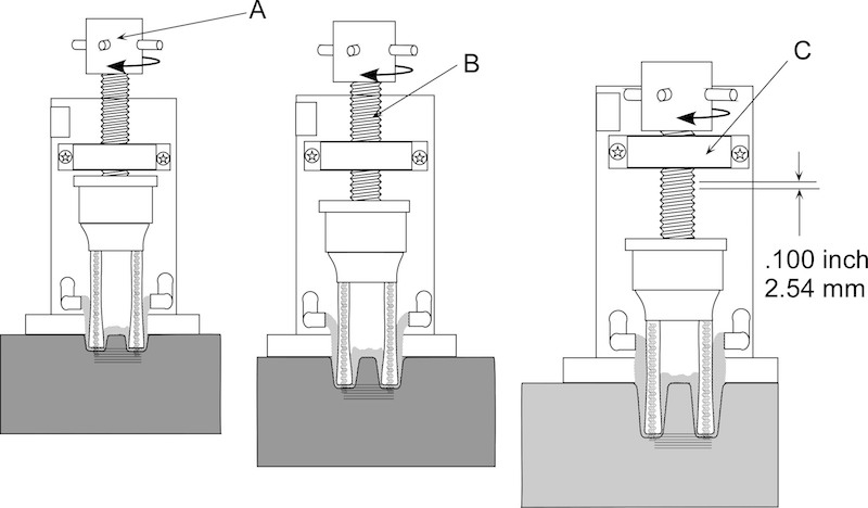
Figure 10. Ultrasonic machining of granite.
Figure 10 shows a basic concept of how the drill worked. The core drill was attached to an assembly that included a horn assembly and transducer and a threaded shaft (Figure 10 - B). While axially oscillating, the assembly was turned by way of a turn knob (Figure 10 - A) through a nut assembly (Figure 10 - C).
This idea, of course, while popular in some circles, was certainly not popular among Egyptologists, one of whom is Denys Stocks, who writes:
Despite this apparent abundance of evidence, many people still argue that these simple tools were not capable of producing the artifacts that survive and, therefore, that there had to be some as yet undiscovered technology that the Egyptians possessed. These supposed technologies include diamond-tipped saws and drills and even the use of sonic waves to cut stone. [10]
Stocks goes on to claim in his article that he had been able to replicate and demonstrate the efficiencies of the tools we “know” were in the ancient Egyptians toolbox. His work is exhaustive and goes to great length in describing every step of his methods, and it includes photographs of bow drills, copper chisels, stone axes, and copper tubes for grinding into diorite using sand as well as an example of a small urn being drilled.
With such a comprehensive and complete study of how simple, primitive tools were applied in prehistory, and with the support of academia behind him, it would seem that the subject of ancient technology was an open-and-shut case. Yet because we have already examined two theories on ancient saws and found them lacking, Stocks’s efforts to prove how the ancient Egyptians drilled granite using core drills must be examined more closely.
Mike Brass, a South African Egyptology student, first advised me of Stocks’s effort to drill granite using a copper tube and sand. I must admit I did not take it seriously as it conflicted with Petrie’s assertions based on his observations of the core in his possession and the idea was counter to my own personal experience and knowledge of the capabilities of drills. Therefore, I did not refer to it when my article was reprinted. I probably should have given it more attention, for it is the simplest method devised because it demands the introduction of the least number of unproven assertions. The materials are already in the archaeological record, and pictorial images can be interpreted as ancient Egyptians using those materials in their working of stone. The experiments by Stocks lodged firmly in the academic record and are referenced by Deiter Arnold in Building in Egypt. [11] This should be enough, we might think, to accept those findings and look no further for answers.
Yet there is that nagging question spiraling around Core 7 in the Petrie Museum. Stocks described the results of a drilling experiment that was conducted in 1999 as part of his involvement with the Lehner/Hopkins Nova obelisk experiment. Regarding a core that he ground out of granite using quartz sand and a copper tube attached to a shaft and manually driven by a bow and sand, he writes:
Horizontal striations similar to the ancient ones on rose granite were visible both in the wall of the hole . . . and upon the core. [12 13]
Stocks’ seemingly innocuous statement actually speaks to the heart of the debate regarding the technology used by the ancient Egyptians to drill granite. Horizontal striations, as opposed to helical grooves, would sink the sonic machining theory in a sea of vibrating quartz quicksand, where it will forever rest and, perhaps, remembered by some as an interesting yet troublesome theory and by others as the product of an overactive imagination.
When we look at Core 7 and the drunken crawl of the groove around its circumference, there seems to be a lack of order and certainty to them. Is it possible that Petrie was mistaken or confused when he described this core? Lucas and Harris were not convinced that his evidence supports his conclusion that jewel teeth were set in bronze saws and tubes to create these grooves, but they did not question his observations that the groove was spiral and not horizontal. In Ancient Egyptian Materials and Industries, they write:
"In my opinion, to suppose the knowledge of cutting these gem stones to form teeth and of setting them in the metal in such a manner that they would bear the strain of hard use, and to do this at the early period assigned to them, would present greater difficulties than those explained by the assumption of their employment. But were there indeed teeth such as postulated by Petrie? The evidence advanced to prove their presence is as follows:
- "(a) A cylindrical core of granite grooved round and round by a graving point, the grooves being continuous and forming a spiral, within one part a single groove that may be traced five rotations round the core.
- "(b) Part of a drill hole in diorite with seventeen equidistant grooves due to the successive rotation of the same cutting point.
- "(c) Another piece of diorite with a series of grooves ploughed out to a depth of over one-hundredth of an inch at a single cut.
- "(d) Other pieces of diorite showing the regular equidistant grooves of a saw.
- "(e) Two pieces of diorite bowls with hieroglyphs incised with a very free-cutting point and neither scraped nor ground out." [14]
Petrie’s observations of a helical groove were explained by Stocks to be the result of the random action of quartz sand in the drilling process. This process produces, for the most part, horizontal striations which he noted in his drilling experiment.[15]
Other experiments were made by Leonart Gorelick and A. John Gwinner of the School of Dental Medicine S.U.N.Y. at Stoneybrook, who show the results of drilling using a copper tube and emery grit, a component of which is magnetite and corundum. Corundum has a hardness of Mohs 9. Gorelick and Gwinner claimed that by using emery, they were successful in grinding out conventric grooves in glass, but indicated that quartz sand would not perform as well. [16]
Seeking to resolve the question of helical versus horizontal grooves, two men set about verifying them by examining the central piece of evidence that was located in the Petrie Museum. John Reid, an acoustic engineer who is noted for his work on pyramid acoustics, and Harry Brownlee, an expert stonemason and sculptor, concluded after their inspection of Petrie's Core 7 that the grooves were horizontal, not helical, as described by Petrie.
In their book Giza the Truth, Ian Lawton and Chris Ogilvie-Herald write:
"They [Reid and Brownlee] make the critical distinction, not effectively made by Dunn, between the horizontal striations that are found on all cores—these being separate grooves, which are on close inspection randomly spaced—and spiral striations, which are genuinely connected spiral grooves. Petrie reports that he found these latter on only one piece, which he examined—our old friend drill core ‘No. 7’, whereon he described four connected spiral turns. Reid and Brownlee have examined and photographed this core in minute detail, and report that even on this they can detect only horizontal striations (see Plate 26); they can only conclude that there may be some confusion in the labeling of the artifact at the museum." [17]
While Lawton and Ogilvie-Herald stress that Petrie found the spiral striations on only one piece, this is not true. As Lucas and Harris state, other examples were found and noted by Petrie:
"Another piece is part of a drill hole in diorite. This has been part of a hole 4 ½” in diameter, or 14” circumference as the seventeen equidistant grooves appear to be due to successive rotations of the same cutting point, we have here a single cut 20 feet in length.” [18]
Thanks to the publication of Lawton’s and Ogilvie-Herald’s book, I now had knowledge of where Core 7 was housed and went to London to examine it myself. I had taken Petrie’s word on his observations of a spiral groove and had made assertions based on his observations. Because of the controversial nature of my theory, and the questions raised by Lawton and Ogilvie-Herald, I suspended those assertions subject to my own observations. It should not have been a surprise to me that not only would I be criticized heavily for my theory of ultrasonic drilling, but also that Petrie’s critical observations, which I used to support my conclusions, would also be questioned and ultimately rejected, for if they were to stand as observed by Petrie, then the theory that ancient drill holes were cut using copper and sand would be difficult, if not impossible, to substantiate.
It is noteworthy that Reid and Brownlee are confident in describing horizontal striations. On a truncated cone such as Core 7, it requires more than visual inspection to determine if a groove with a slight pitch, or distance between the start and end point in a 360 degree turn, is helical or horizontal. Petrie provided dimensions in his analysis, while neither Stocks nor Reid nor Brownlee nor Lawton nor Ogilvie-Herald have produced any measurements to support their assertion that Petrie’s observations were incorrect—only that they “had examined the core in minute detail.”[19] Petrie, on the other hand, following his lecture to the Royal Anthropological Institute on April 24, 1883, in which he received comments from several attendees who proposed that his findings were more likely to have been produced using abrasives, such as emery powder or corundum, provided a footnote for his article, that appeared in the RAI’s Journal the following year, and provided a further analysis he had made of the core where he had specific measurements of the groove at 90 degree angles around its 360 degree circumference four times.
"In consequence of remarks on the granite core I have examined it more carefully. It offers apparently a complete proof that the lines were cut by fixed points, and not by rubbing of a loose powder; for the grooves are cut as deeply in the quartz as in the feldspar. And the feldspar being somewhat rubbed down, by general friction, the lines are actually cut through a greater thickness in the harder quartz which stand above the feldspar. Now no loose power could cut down to exactly the same depth in material of different hardness like quartz and feldspar; still less would it cut more out of the prominent quartz; but a fixed point must cut to the same depth in each material.
"The spiral was described as a “drunk screw”; I therefore traced very carefully a normal plane at right angles to its axis and measured off the distances to the spiral: they are thus, at successive quarter turns in inches."[20]
Petrie’s Core Measurements.[21]
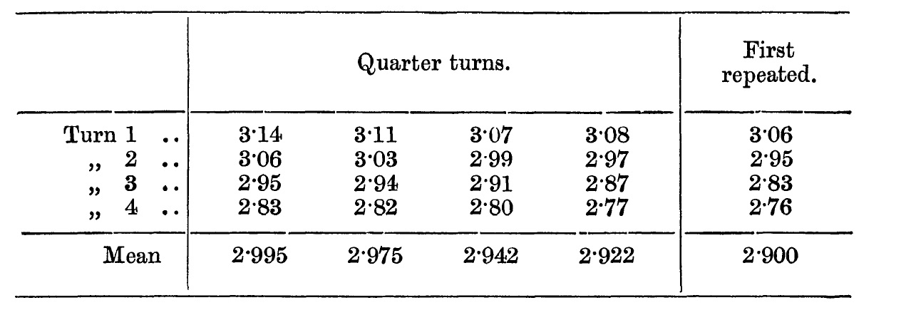
Petrie's Published Measurements.
| Rotation | 0 Degrees | 90 Degrees | 180 Degrees | 270 Degrees | 360 Degrees | Pitch | ||||||
|---|---|---|---|---|---|---|---|---|---|---|---|---|
| inch | cm | inch | cm | inch | cm | inch | cm | inch | cm | inch | cm | |
| Turn 1 | 3.14 | 7.98 | 3.11 | 7.90 | 3.07 | 7.80 | 3.08 | 7.82 | 3.06 | 7.77 | 0.08 | 0.2 |
| Turn 2 | 3.06 | 7.77 | 3.03 | 7.70 | 2.99 | 7.59 | 2.97 | 7.54 | 2.95 | 7.49 | 0.11 | 0.28 |
| Turn 3 | 2.95 | 7.49 | 2.94 | 7.47 | 2.91 | 7.39 | 2.87 | 7.29 | 2.83 | 7.19 | 0.12 | 0.30 |
| Turn 4 | 2.83 | 7.19 | 2.82 | 7.16 | 2.80 | 7.11 | 2.77 | 7.04 | 2.76 | 7.01 | 0.07 | 0.18 |
| Average | 2.995 | 7.607 | 2.975 | 7.557 | 2.942 | 7.473 | 2.922 | 7.422 | 2.99 | 7.59 | 0.095 | 0.241 |
Metric dimensions and pitch added by C. Dunn
"Here if there were any “drink” in the screw it would appear as an irregularity in the order of the means of each quarter; whereas they proceed as regularly as the small variations due to the texture will permit. There is not 1/100” irregularity in the mean spiral, though the pitch is 1/10”.
"The spiral could not be produced by the mere withdrawal of the tool as it is too deeply cut to have been made without great force and it is wholly unlikely that a tool should be withdrawn with such regularity. Again as there would be from 1/10” to 2/10” of loose dust between the tool and the tapered end of the core, the cutting points of the crown would not reach it on withdrawal, and if they did so accidentally they would not touch the core in a continuous line all round, but only on one side.
"That there are lines on modern drill cores is not the point. These cores are not tapered and hence the lines there can be produced by the crown.
"On examination, it seems most probably to me that the coning was not due to stones set in different projections, but rather by a row of stones up the side projecting uniformly. Then when the top weight was tilted over to one side, or did not balance truly on the drill head, it would drag the drill over and thus make it enlarge the hole and taper the core as it cut downwards.
"An engineer present has remarked to me that the manufacture of hammers good enough to dress down granite on such a very large scale, as in the Great and Third Pyramids, implies almost as much skill as any other method of dressing the stones."[22]
It is easy to be mistaken when we examine Petrie’s Core 7 to try to determine if the grooves are spiral or horizontal. It is especially easy to make a mistake if we examine a photograph in which the core is tilted to one side—such as in the photograph pictured in Giza the Truth. Before traveling to England to examine the core firsthand, I suspected that their conclusions were in error after I examined their photograph in my graphics program. Figure 11 - A shows Core 7 as seen in Giza the Truth. Figure 11 - B shows Core 7 in a corrected orientation with a vertical central axis center . A construction reference frame is provided so that the tilt can be seen and a horizontal dashed line was added to compare it with the grooves on the granite core. The horizontal dashed line indicates that the grooves appear to be horizontal in Figure 11 - A and are not horizontal in correct orientation in Figure 11 - B.
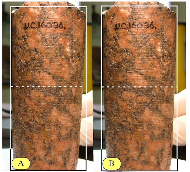
Figure 11. Tilted orientation of Core 7 .
Jon Bodsworth of the UK has also taken a photograph of the granite Core 7, and it is frequently displayed on the internet tilted on a similar angle as the photograph in Giza the Truth and used to deny Petrie’s spiral thread observations. To further explain the problem with analyzing a tapered thread when it is tilted on an angle, I have Figure 12, which is a common ¾ -inch pipe thread with 14 TPI (threads per inch). As you can see on the left, the pipe is tilted on an angle similar to the angle of Core 7 in Figure 11 - A. The horizontal reference line indicates that the thread is horizontal. The pipe on the right is in the correct orientation, and the reference line shows the thread as it should be—the line travels from the crown of the thread to the root with 180 degrees of the diameter viewed. A complete turn would find the line on the crown of the thread seen above the root on the left.
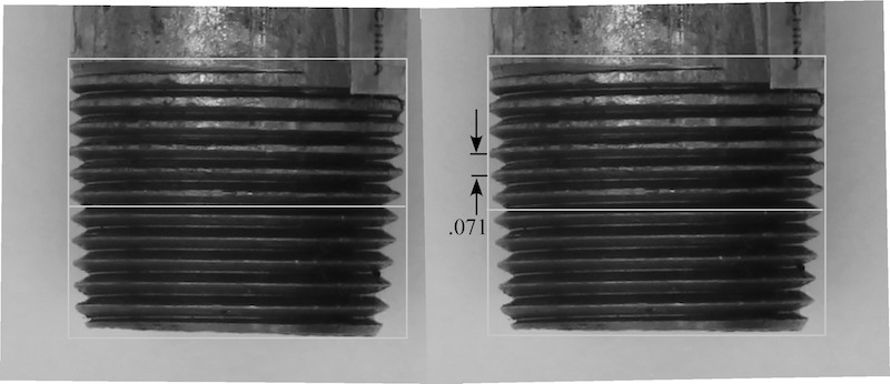
Figure 12. Threaded pipe tilted at the orientation of Core 7.
The problem with analyzing a photograph of Core 7 is that, as Petrie pointed out, the groove wanders from side to side from a theoretical perfect helix. He noted that the groove doesn’t vary more than 1/100 inch (0.010 inch; 0.254 millimeter). Yet with one thread wandering either toward or away from an adjacent thread, the published photographs by Lawton, Ogilvie-Herald, and Bodsworth have served to weaken Petrie’s argument.
Notwithstanding my suspicions, I had to travel to London to have a firsthand look at the evidence. I contacted a colleague, Nick Annies, who lives near Cambridge, and he kindly arranged for us to visit the Petrie Museum and assisted me in the examination of the core. I am greatly indebted to him for his generous hospitality and support while I was in England during this period. As I pondered how to measure the groove on the core, I considered a fixture that would rotate it while a stylus traced the groove. This seemed too elaborate, even though it would have provided quantitative measurements. I didn’t intend to measure every departure from a true helix that the groove may follow, but instead, I wanted to determine whether, as Petrie measured, it was actually a helix at all. I had only to confirm Petrie’s observations that this was not a horizontal groove that began and ended at the same point—regardless of where that point was on the circumference.
The simple and most visual test to demonstrate this would be to wrap a common white cotton thread around the core, making sure it followed the same groove. This test was performed on November 15, 1999. Some readers objected to my observations and continued to accept Reid and Brownlee’s observations as factual, even though, unlike Petrie and me, they had not produced anything other than a photograph of a tilted core and an opinion based only on that photograph. After examining the core myself, I was convinced of the correctness of Petrie’s observations, but I realized that I had to gather even better evidence to support them.
Figure 13. Chris Dunn beginning to examine Core 7 in the Petrie Museum.
Figure 13 a. Examining the core using 50X microscope.
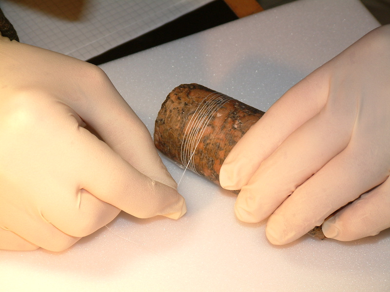
Figure 13 b. Core 7 with white cotton thread wrapped following a spiral groove.
Figure 13 c. Indicator Depth Gage.
Figure 13 d. Inspecting the depth of the groove with depth gage.
Gas turbine engine manufacturing engineers are very familiar with cones large and small with varying ratios of height to top and bottom diameters. Sheet metal cones start out as a flat blank. They can either be rolled without any geometric features machined around the body or the cone, or geometric machined features can be applied when the metal is a flat blank. Today, this work is performed with computer software where an engineer can create a cone and apply geometric features to the surface of the cone and then unwrap the cone into a flat blank using special software algorithms to provide the geometry as it needs to be machined in the flat blank. With this in mind, and with my own testimony as well as Petrie’s dismissed, it became imperative that I obtain a latex impression of the core so that I could present the grooves on a flat blank so that the entire surface of the cone is visible and to dismiss any doubt about the correctness of Petrie’s observations and measurements.
Following my first visit to the Petrie Museum, I was contacted via e-mail by a geologist in England who was also interested in Petrie’s Core 7 and had read both Petrie’s work and mine. Malcolm McClure had retired from British Petroleum and had a passion for investigating anomalous events and artifacts from history and the present. McClure had found solutions to most mysteries, he told me, but he had still not been satisfied with what has been written regarding the grooves on Petrie’s Core 7. He was not convinced they were horizontal, but he was also not quite convinced by Petrie or me that they were spiral either. I explained my dilemma to Mr. McClure and said that I needed to examine the core again and also have a latex impression made of the core so that the grooves could be examined in two dimensions laid out flat. He contacted Dr. Stephen Quirke, the curator of the museum, and I gained permission to perform another analysis.
I arrived in England on March 30, 2003, and enjoyed the generous hospitality of Graham Hancock and his wife Santha Faiia, who provided me with accommodation in their London home. The following day I met Mr. McClure and Nick Annies, who would assist by taking photographs with his digital camera, and after breakfast at the University College London student hall, we headed over to the Petrie Museum.
I performed the same thread wrap around the core with Mr. McClure and Mr. Annies observing closely. After achieving sixteen wraps around the core, I could sense that Mr. McClure was anxious to try it himself, and he eagerly took the core and thread from me and set to work wrapping the thread around the core, being careful to fit it into the groove as he went. After performing several wraps himself, he declared that he was speechless, and pondered whether he, being the observer and knowing of the spiral claim for the core, had affected the outcome. This is because there are discontinuities in the groove, which is why Petrie noted only four continuous turn. Using the thread, and reaching a point in the turn where a discontinuity exists, a decision is made as to the direction the thread takes before the discontinuities to the place where it picks up again.
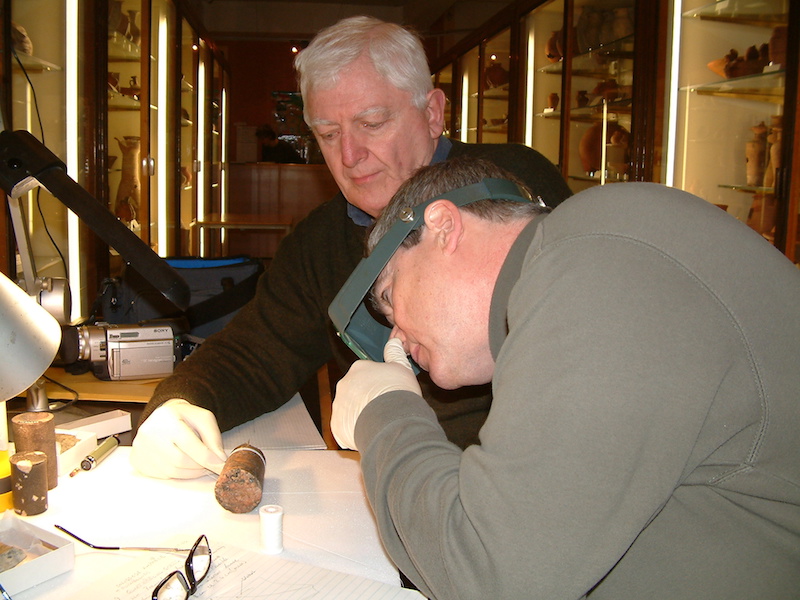
Figure 14. Geologist Malcom McClure wraps the thread.
After our work was finished, we met with Dr. Stephen Quirke and discussed the possibility of having a latex mold made of the core. Dr. Quirke said he would forward the request to the conservationist, James Hale. He also indicated that he looked forward to seeing the controversy surrounding this artifact eventually settled. Evidently, he fielded another request from a person who wished to perform an analysis on the core to see if, by rotating it and putting a gramophone needle in the groove it might reveal untold secrets from the past.
The latex peel provides another view of Core 7 and valuable information regarding the spiral groove’s regularity and frequency along the length of the core. I received the latex impression in the mail in 2003, but my time and attention shortly thereafter became consumed with personal and family matters, and it sat for several years before I examined it. When I finally began to work with it, the edges had begun to split, so I knew that my intention of mounting it on a tapered mandrel would not work. Instead, I inserted a plastic tube on its interior and cut two square holes along its length near the splits. Then I cut a line between the square holes and continued with the cut to join with the splits at the ends (see Figure 15.)
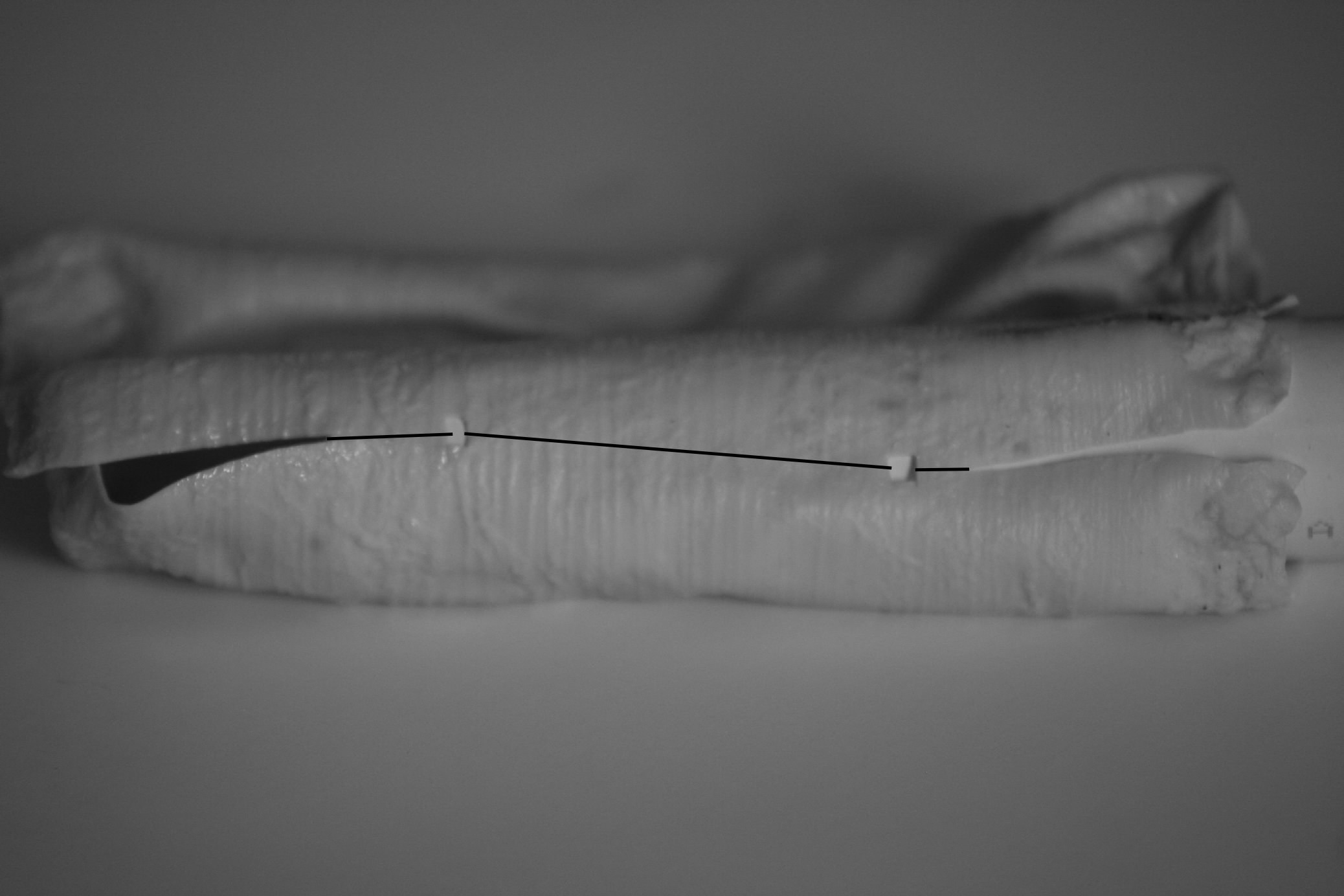
Figure 15. A latex impression of Core 7 showing notches and cut lines.
It was my intention to unfold the latex into a flat blank and examine the grooves with the blank oriented to the notches. If the grooves were horizontal, they would appear as an arc that started and ended at the same point. Orienting the blank by using the notches that were once joined, I could analyze the entire surface. As seen in Figure 16, points A and B identify the start and end point of an arc that would be horizontal or would have the same start and end point. Points C and D do not have the same start and end point and, therefore, represent a spiral groove. Point C joins with point F, completing one turn of the spiral and starting another.
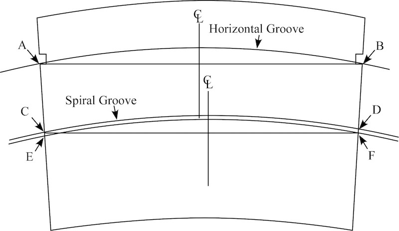
Figure 16. Geometry of a spiral groove on the unfolded impression of Core 7.
I then flattened the latex on a white piece of construction board and photographed it using an 8-megapixel camera. Figure 17 has been color enhanced in order to highlight the grooves, and I have applied construction lines and arcs. Readers are welcome to perform their own analysis of these photographs, but my final conclusion based on Malcolm McClure’s and my on-site inspection as well as the flat layout of the surface with arcs applied is that the groove around the Petrie Core 7 is a spiral rather than individual horizontal striations as claimed by Reid and Brownlee and others. Moreover, this spiral groove travels the full length of the core, and any discontinuities are due to the ripping out of the mica—a constituent of the granite—with some discontinuities seen as faint lines on the latex peel, but on the granite core they cannot be seen with the naked eye. On the whole, the quartz seemed to be fairly intact, but the extent of the ripping in the mica was extensive.
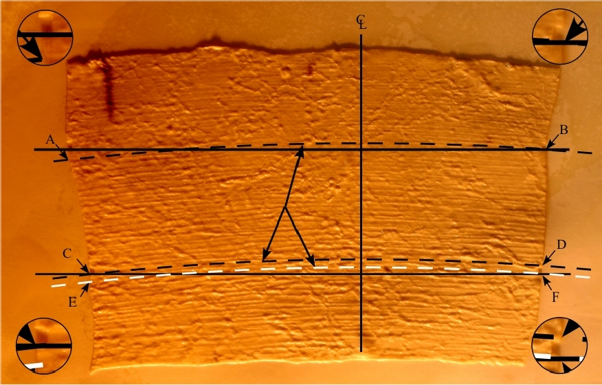
Figure 17. Flat layout of the latex impression of Core 7.
Taking into consideration Petrie’s own account, my inspection in 1999, and Malcolm McClure’s and my inspection in 2003, along with analysis of the latex impression of the core, the question regarding whether the groove is horizontal or spiral appears to be answered. The groove follows a continuous helical path around the circumference of the core down its full length, with periodic discontinuities along the way.
As seen in the close-up photographs of the latex impression (Figure 18), the irregularities in the groove cannot be overlooked and seem to argue against the theory that a tool with a precise mechanism for advancement was used. These inaccuracies, along with random movement of material removed from the hole during the process, though, support a strong argument that either a manual or an inaccurate, mechanically controlled tool played some part in performing the work. Upon closer inspection, I find no evidence to support the theory that ultrasonic drilling was employed. In fact, there is an abundance of evidence when we look closely at the surface of the latex to argue against this theory.
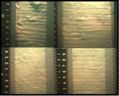
Figure 18. Close-up photographs of the latex impression of Core 7 showing random bubbles and diverting runs on the surface.
Petrie’s measurement of 0.100 inch (2.54 millimeters) distance between the grooves is not supported by the evidence seen in Figure 17. The grooves seen here range from 0.050–0.080 inch (1.27–2.03 millimeters), though they depart at places and are closer to what Petrie measured. Also, the depth of the groove, as seen in Figure 18, varies to a maximum depth of 0.0075 inch (0.190 millimeter). Inexplicable features that become more prominent when seen on the magnified surface are the raised areas where, presumably, material was by some means gouged out in the drilling process. They appear like bubbles on the surface. The latex impression also clearly reveals an addition to the grooves with short runs traveling from one groove to the next in a relatively short distance. In some areas, the additional run is almost parallel to the axis of the core. This feature is not clearly evident on the core itself and is not mentioned by Petrie or any other observer that I am aware of.
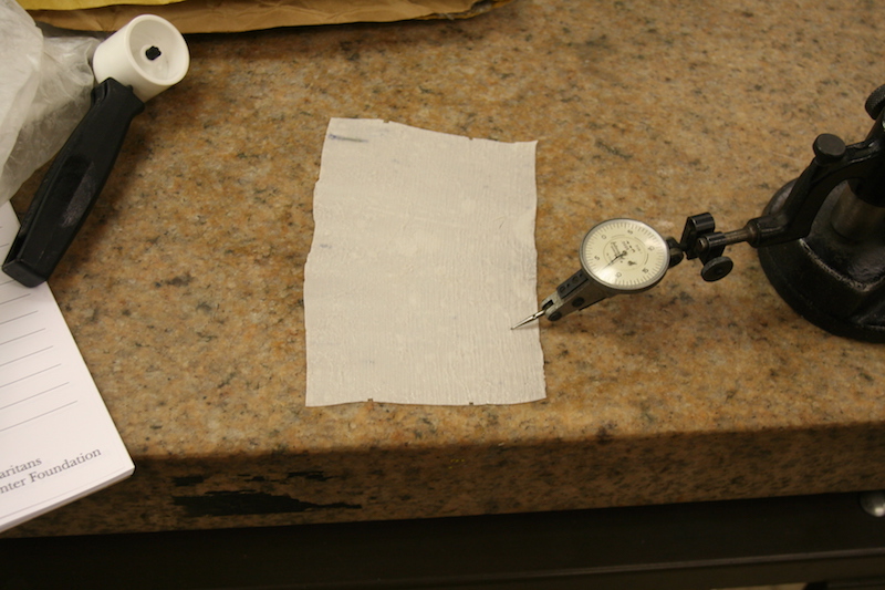
Figure 19. Inspecting depth of groove on latex impression.
After trying, but failing, to obtain a good photograph of Denys Stocks’s drilling experiments, other than what was in his published articles and book, I was left wondering whether there can be any reasonable link between the methods he used and those the ancient Egyptians used and impressed upon their granite. Though Mr. Stocks indicated that final twisting of the drill at the conclusion of the drilling created the spiral grooves, it is hard to believe that random scratches from a reciprocating bow drill would organize themselves into a continuous spiral down the length of the core with a few twists of the drill. Nonetheless, Stocks is the man with the evidence that allowed him to form this opinion, so without access to his evidence, I was left with no option but to drill a piece of granite myself.
I obtained a piece of red granite from a local monument dealer and defined the outside diameter of a 2.125 inch (5.4 centimeter) copper tube on the top of a flat surface of the granite. After chiseling a shallow groove around the marked circle using a carbide tipped drill point I then poured silicon carbide 80 mesh grit into the groove. (Silicon carbide has a Mohs hardness of 9.5 whereas quartz sand has a hardness of Mohs 7, the same hardness as the quartz in the granite). I then began to rotate the drill assembly, which was weighted with 60lb (27.215kg) lifting weights, clockwise and counter clockwise. At first I tried using a bow string with leather cord but found it inefficient and awkward so I equipped the assembly with a common machine handle and rotated it without the bow. I doubt that the granite knew the difference.
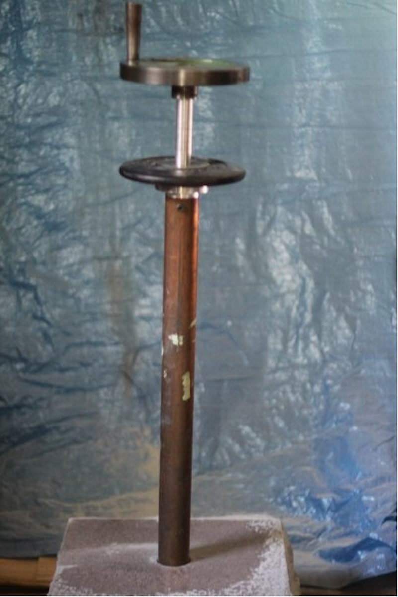
Figure 20. Copper tube drill rig assembly.
After reaching a depth of about a .25 inch, I switched to a diamond hole saw and took the hole to its maximum depth of 1.64 inch (4.165 centimeter). Then I inserted the copper tube again and worked the hole down further. Having my hands in contact with the drill assembly was beneficial as I was able to feel when fresh grit was needed to be introduced into the slot as it didn’t take long for the grit to wear down to nothing but dust and the difference in the vibration through the drill assembly between fresh grit and dust was substantial. To remove the old grit and waste from the round slot I had the benefit of compressed air and knowledge of the health risks of breathing silicon carbide dust, so I donned a paper mask before blowing the dust out and made sure that the air cleared before taking it off again.
As I worked the tube deeper into the granite, I consciously wobbled it more than I needed to so that the surfaces of the core and the hole were ground away. After reaching a depth of 2.265 inch (6.73 centimeter) I used a copper wedge shaped mandrel and attempted to knock the core out of the hole. Stocks does not say what material his chisels were made from, but I assume they were copper as the ancient Egyptians allegedly didn’t have steel. If so, he was more successful than I because my copper wedge wouldn’t budge the core and became deformed with a step as the granite resisted its inherent soft characteristics. Ultimately, I resorted to a steel chisel and with one blow the core gave way. The statistics of the hole, core and drills are as follows:
| Statistics of hole, core, and drill | |
|---|---|
| Hole | |
| Diameter at the top | 2.18 inches (5.54 centimetres) |
| Depth | 2.265 inches (6.73 centimetres) |
| Core | |
| Diameter at the top | 1.935 inches (4.914 centimetres) |
| Diameter at the bottom | 2.125 inches (5.019 centimetres) |
| Copper Tube | |
| Outside diameter | 2.125 inches (5.397 centimetres) |
| Inside diameter | 2.00 inches (5.08 centimetres) |
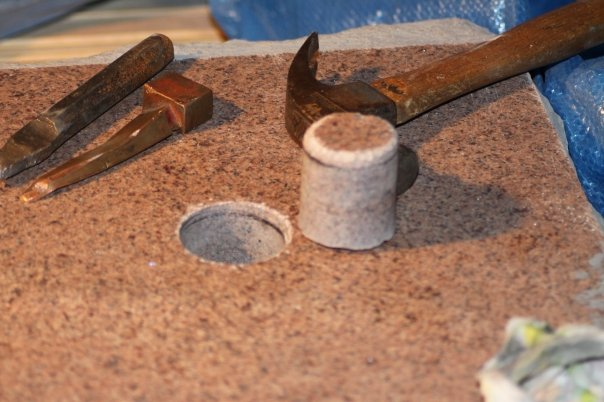
Figure 21. Hole and core with chisel wedge and hammer.
While I worked the tube by tilting it intentionally to the side after using the diamond hole saw, striations made by the diamond were not all ground away. The areas where they exist on the core are evident in Figure 22. The larger percentage of their marks, however, were removed as the tube ground the hole to depth. The diamond hole saw striations reveal that another method, suggested by Petrie, does not produce the kind of spiral groove evident on core 7. The area worked with abrasive and copper similarly do not produce the striations revealed in ancient Egyptian holes, i.e., Figure 22 top left and top right, which are reflected on core 7.
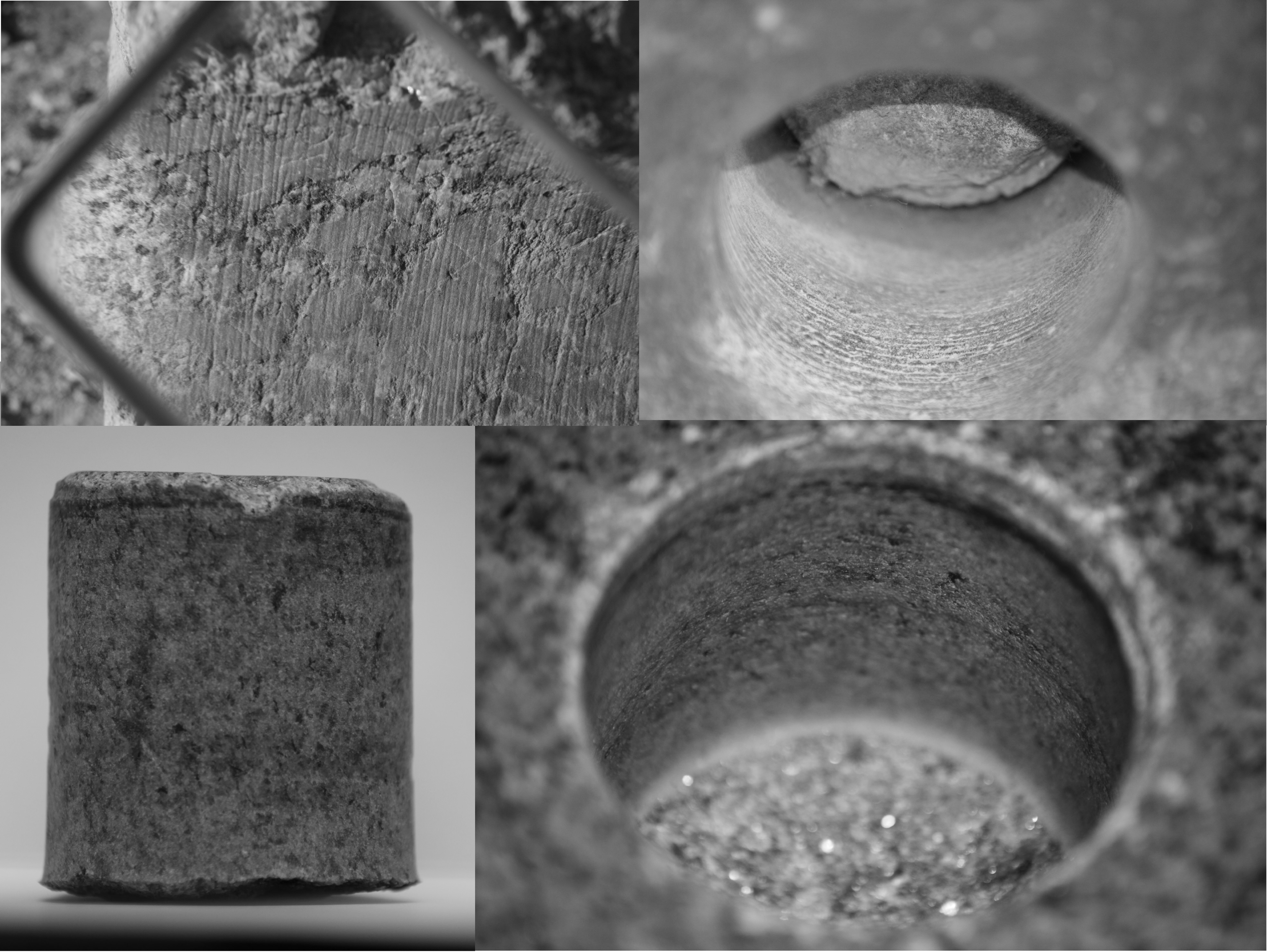
Figure 22. Top left: Drilled hole at Abu Ghorab (courtesy Patrice Pooyard). Top right: Close up of drilled hole in the Valley Temple lintel block. Bottom left and right: Drilled hole and core using a copper tube and silicon carbide 80 mesh abrasive.
Another feature that was evident as a result of my drilling experiment, and which also serves to dispel both the copper and abrasive and the theory of ultrasonic drilling, is the finish on the surface of the hole and core. When using sand, or any other abrasive to remove material, what other finish would we expect other than a sanded finish? Even if I was able to dig deeper grooves into the granite, as I am sure Stocks was able to, the surface finish on the granite using an abrasive method is unlike the surface finish on core 7 or on the holes ancient cores came out of. As we can see in Figure 11 core 7 is not sanded, but appears to have a polish to it.
With respect to what methods the ancient Egyptians used to create core 7, I have no real answers. However, to replicate the core and holes, an experimentalist might consider softening the granite using heat. Does the burnished finish on the surface of core 7, as well as the random runs between the grooves and the proliferation of depressions where mica is removed, along with the spiral groove itself, indicate that if the granite was brought close to its melting point, then all of these characteristic may be replicated?
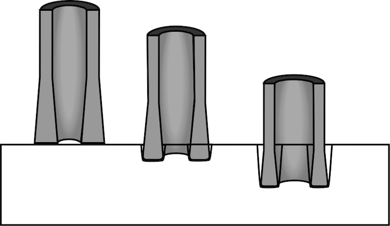
Figure 23. Tool geometry for explaining taper on core and hole.
Such a method may involve using a tool that sacrifices its material in the process, as depicted in Figure 23. But until an answer is found, Petrie’s core 7 will remain in its case at the Petrie Museum as evidence of one of Egypt’s lost technologies.
(Pl. XIV)
End Notes
[1] Comment by Mark Lehner at the American Association for the Advancement of Science Convention in Chicago, 1992.
[2] Eric P. Uphill, A Bibliography of Sir William Matthew Flinders Petrie (1853-1942) Source: Journal of Near Eastern Studies, Vol. 31, No. 4 (Oct., 1972), pp. 356-379 Published by: The University of Chicago Press Stable URL: http://www.jstor.org/pss/543795. Accessed: 08/01/2010 22:08
[3] “Scholars Dispute Claim that Sphinx Is Much Older,” New York Times, February 9, 1992.
[4] Ibid.
[5] Henry Hodges, Technology in the Ancient World (New York: Barnes and Noble Books, 1970), 185.
[6] William Flinders Petrie, Pyramids and Temples of Gizeh, 77–78.
[7] Ibid., 74–75.
[8] Christopher Dunn:
- “Advanced Machining in Ancient Egypt”; The Giza Power Plant (Rochester, Vt.: Bear and Company/Inner Traditions, 1998)
- “Advanced Machining in Ancient Egypt?” in Stanley Schmidt, ed., Analog Anthology (New York: John Wiley and Sons, 1990)
- “Hi Tech Pharaohs,” Part 1, in Amateur Astronomy & Earth Sciences Magazine (December 1995)
- “Hi Tech Pharaohs,” Part 2, in Amateur Astronomy & Earth Sciences Magazine (January 1996)
- “Hi Tech Pharaohs,” Part 3, in Amateur Astronomy & Earth Sciences Magazine (February 1996)
- “An Engineer in Egypt,” in Atlantis Rising 8, August, 1996.
[9] William Flinders Petrie, Pyramids and Temples of Gizeh, 75 - 77.
[10] Denys A. Stocks, “Technology Innovators of Ancient Egypt,” in Ancient Egypt 7, no 3 (December/January 2007).
[11] Deiter Arnold, Building in Egypt: Pharaonic Stone Masonry. New York: Oxford University Press, 1991), 266, 268 n64.
[12] Denys A. Stocks, “Testing ancient Egyptian granite-working methods in Aswan, Upper Egypt, Antiquity 75 (2001): 93;
[13] Denys A. Stocks, Experiments in Archaeology: Stoneworking Technology in Ancient Egypt (London: Routledge, 2003), 135.
[14] A. Lucas A., and J. R. Harris, Ancient Egyptian Materials and Industries (New York: Dover Publications, 1999), 70–71.
[15] Denys A. Stocks, Experiments in Archaeology, 128.
[16] Leonard Gorelick and A. John Gwinnet, Philological and Archaeological Evidence for the Use of Emery in the Bronze Age Near East, Journal of Cuneiform Studies, Vol. 40, No. 2 (Autumn, 1988), 195-210. Published by: The American Schools of Oriental Research Stable URL: http://www.jstor.org/stable/1359662 (accessed 01/11/2010).
[17] Ian Lawton, and Chris Ogilvie-Herald, Giza the Truth: The People, Politics & History Behind the World’s Most Famous Archaeological Site, 217.
[18] William Flinders Petrie, On the Mechanical Methods of the Ancient Egyptians. The Journal of the Anthropological Institute of Great Britain and Ireland, Vol. 13, (1884), 90.
[19] Ian Lawton, and Chris Ogilvie-Herald, Giza the Truth: The People, Politics & History Behind the World’s Most Famous Archaeological Site, 217.
[20] William Flinders Petrie, On the Mechanical Methods of the Ancient Egyptians. The Journal of the Anthropological Institute of Great Britain and Ireland, Vol. 13, (1884). 103,104
[21] Ibid, 104. [Note: Added to Petrie’s table are metric measurements and distance (pitch) between the start point and end point of each turn, which have also been changed from quarter turns to degrees.
[22] Ibid, 104.